Technologies
To the preceding section: Methodology
The partners of the SALUTE project will develop two alternative technologies as liner concepts:
- a semi-active version based on a MEMS transducer
- an active version based on the Electroacoustic Absorber concept.
MEMS-type acoustic absorber
to be updated soon
Electroacoustic absorber concept
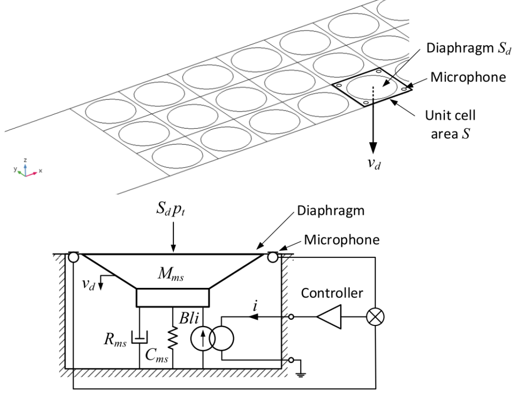
This section summarizes the concept of Electroacoustic absorber to be developped in the context of the SALUTE project. Further information might be found in .

In this concept, the acoustic liner is composed of a 2D surface of small loudspeakers, subject to an external sound pressure wave. Each loudspeaker is individually controlled through a feedforward strategy described in the picture to the right: by sensing the front sound pressure ![]() with microphones, the controller drives the loudspeaker with an electric current
with microphones, the controller drives the loudspeaker with an electric current ![]() , assigning the loudspeaker membrane velocity
, assigning the loudspeaker membrane velocity ![]() , through a control function Θ defined in the frequency domain: as
, through a control function Θ defined in the frequency domain: as ![]() . This control scheme defines then an Electroacoustic Absorber, as defined in .
. This control scheme defines then an Electroacoustic Absorber, as defined in .
Controlling the acoustic impedance of the loudspeaker membrane
Since the effective acoustic impedance (that eventually defines the sound absorption performance) presented by each membrane is defined in the frequency domain by ![]() , the whole dynamics of the controlled electrodynamic loudspeaker, subject to an incident pressure
, the whole dynamics of the controlled electrodynamic loudspeaker, subject to an incident pressure ![]() , leads to:
, leads to:
where ![]() designate the mechanical mass,
designate the mechanical mass, ![]() the mechanical resistance, and
the mechanical resistance, and ![]() the mechanical compliance (inverse of stiffness) of the membranes,
the mechanical compliance (inverse of stiffness) of the membranes, ![]() is the electrodynamic factor, and
is the electrodynamic factor, and ![]() the surface of the membranes.
the surface of the membranes.
What happens when there is no control?
When the loudspeaker is not controlled (ie. current ![]() ) it already behaves as a mass-spring-losses system with acoustic impedance
) it already behaves as a mass-spring-losses system with acoustic impedance
with resonance frequency ![]() and resonance quality factor determined by
and resonance quality factor determined by ![]() . The absorption capability of the uncontrolled loudspaker is then limited to a rather narrow frequency range around resonance, depending on the
. The absorption capability of the uncontrolled loudspaker is then limited to a rather narrow frequency range around resonance, depending on the ![]() factor, and might be not optimal depending on the value of
factor, and might be not optimal depending on the value of ![]() .
.
Controlling the loudspeaker allows modifying its dynamic response to the acoustic pressure
At resonance, the sound absorption can be optimized by modifying the value of effective resistance. Also, it is possible to broaden the frequency range where the membrane is mostly damping (lowering ![]() ), or even change the resonance frequency, by modifying the effective mass and compliance of the membrane. This is exactly the objective of the active control achieved through the control function
), or even change the resonance frequency, by modifying the effective mass and compliance of the membrane. This is exactly the objective of the active control achieved through the control function ![]() .
.
We can then define a target acoustic impedance ![]() to achieve, as a Single-Degree-Of-Freedom (SDOF) resonator of effective mass
to achieve, as a Single-Degree-Of-Freedom (SDOF) resonator of effective mass ![]() , resistance
, resistance ![]() and compliance
and compliance ![]() , so that:
, so that:
The target acoustic impedance takes the form of a mass-spring-damper system, with resonance frequency ![]() , where
, where ![]() is the natural resonance frequency of the loudspeaker membrane.
is the natural resonance frequency of the loudspeaker membrane.
Such target then determines the control law achieving the specified target impedance as:
{\color{red}\Theta_t(\omega)}=\dfrac{S_d}{B\ell}\dfrac{{\color{red}Z_{st}}-Z_{ms}/S_d}{\color{red}Z_{st}}=\dfrac{S_d}{B\ell}\dfrac{-\omega^2({\color{red}\mu_1}-1)M_{ms}+j\omega(S_d {\color{red}R_{at}}-R_{ms})+\frac{{\color{red}\mu_2}-1}{C_{ms}}}{-\omega^2({\color{red}\mu_1})M_{ms}+j\omega(S_d {\color{red}R_{at}})+\frac{{\color{red}\mu_2}}{C_{ms}}}SALUTE: upgrading the electroacoustic absorber liner prototype for real engine architecture integration
In SALUTE, this prototype will be upgraded, following the following axes:
- installation of optimized loudspeakers for better performance
- installation of microphones supporting higher sound pressure levels for less sensitivity to flow noise
- implementation of advanced control strategies, such as Multiple Degrees Of Freedom (MDOF) resonators and impedance gratings along the surface
- mitigation of stability issues with additional passive treatments at high frequencies
- upgrade from 2D (ie. flat) to curved surfaces for better integration in a nacelle
- development of simulation tools for coupling the fluid dynamics and the active control boundaries
To the next section: Impact
